Hotpoint Stove Manual: A Comprehensive Guide
This manual provides essential guidance for Hotpoint stove owners‚ covering everything from model identification to troubleshooting and maintenance․
Locating your stove’s model number – often found inside the oven door frame‚ on the back panel‚ or behind the lower drawer – is crucial for accessing specific information and replacement parts․
Understanding Your Hotpoint Stove
Hotpoint stoves are renowned for their reliability and functionality‚ but understanding their specific features is key to optimal performance․ Identifying the model number is the first step‚ as it unlocks access to tailored manuals and support․
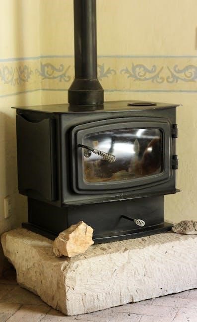
Whether you have a modern digital model or a vintage appliance like the RJ745G0T1BG‚ knowing its components – oven heating element‚ surface burners‚ and control panel – is vital․
Online communities‚ such as Reddit’s r/appliancerepair‚ emphasize the importance of photos when locating model numbers on older stoves․
Proper appliance registration‚ recording model and serial numbers‚ ensures efficient service and access to parts․
Locating the Model Number
Finding your Hotpoint stove’s model number is paramount for accessing accurate manuals‚ ordering replacement parts like drip pans‚ and receiving effective support․ Experts consistently recommend checking three primary locations: inside the oven door frame‚ on the back panel of the stove‚ and behind the drawer situated below the oven cavity․
If the number remains elusive‚ particularly with vintage models‚ posting a clear photograph on online forums like r/appliancerepair can be incredibly helpful․ Remember‚ the model number is essential‚ especially for stoves with unique burner designs‚ ensuring compatibility when sourcing replacements․
Inside the Oven Door Frame
The oven door frame is a primary location to find your Hotpoint stove’s model number․ Carefully inspect the perimeter of the frame‚ looking for a small metal plate or a sticker․ This plate typically contains essential appliance information‚ including the model number and serial number․
Often‚ the model number is prominently displayed‚ though it may be partially obscured or require a closer look․ Ensure good lighting and clean the area if necessary to clearly view the information․ This location is frequently the easiest and quickest way to identify your specific Hotpoint stove model․
On the Back Panel
Another common location for the model number is on the back panel of your Hotpoint stove․ Accessing this area requires caution‚ as you’ll need to carefully pull the stove away from the wall․ Always disconnect the power supply before attempting this!
Look for a metal data plate affixed to the back panel․ This plate will contain the model number‚ serial number‚ and potentially other technical specifications․ The model number is vital for ordering compatible parts and accessing specific troubleshooting guides․ Remember safety first when accessing the back of the appliance․
Behind the Drawer Below the Oven
A frequently overlooked spot to find your Hotpoint stove’s model number is behind the drawer located directly below the oven․ Carefully slide the drawer completely open and then remove it from its tracks․
Once the drawer is removed‚ inspect the opening where the drawer was housed․ The model number is often affixed to the back wall of this compartment‚ typically on a sticker or metal plate․ This location provides a convenient and easily accessible spot for this crucial identifying information․ Remember to reinstall the drawer securely after locating the number․
Essential Components & Their Functions
Understanding the core components of your Hotpoint stove is vital for safe and effective operation․ The oven heating element‚ typically located at the bottom of the oven‚ converts electricity into heat for baking and roasting․
Surface burners‚ whether traditional coils or smooth top designs‚ provide heat for cooking in pots and pans․ The control panel serves as the central hub‚ allowing you to select cooking modes‚ temperatures‚ and timer settings; Familiarizing yourself with these key elements ensures optimal performance and longevity of your appliance․
Oven Heating Element
The oven heating element is a critical component responsible for generating the heat needed for baking‚ roasting‚ and broiling․ Typically found at the oven’s bottom‚ it transforms electrical energy into thermal energy․
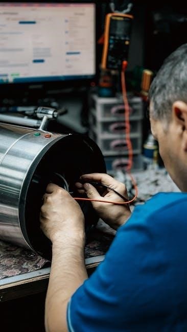
A malfunctioning element will result in the oven not heating or uneven temperature distribution․ Identifying a faulty element often involves visual inspection for breaks or damage‚ or using a multimeter to test for continuity․ Replacement is a common repair‚ and ensuring you have the correct element for your specific Hotpoint model is paramount for safe and effective operation․
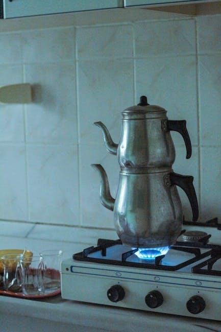
Surface Burners (Coil‚ Smooth Top)
Hotpoint stoves utilize various surface burner types‚ including traditional coil burners and modern smooth top (ceramic or glass) burners․ Coil burners rely on electrical resistance to generate heat‚ while smooth top burners use radiant elements beneath the surface․
Troubleshooting burner issues often involves checking for proper electrical connection‚ ensuring the igniter is functioning correctly (for coil burners)‚ or verifying the smooth top surface is clean and free of obstructions․ Drip pans are essential for containing spills‚ especially with three-slot burner designs‚ and compatible replacements are vital for maintaining cleanliness․
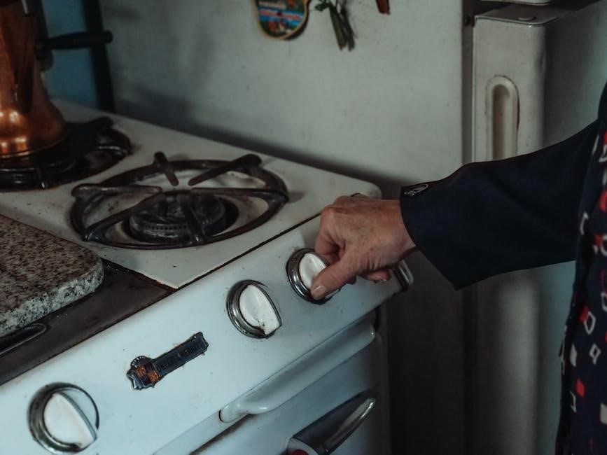
Control Panel Overview
The Hotpoint stove control panel serves as the central hub for operating all oven and cooktop functions․ Digital displays present settings‚ temperatures‚ and potential error codes‚ requiring careful decoding for effective troubleshooting․
Control panels typically feature burner controls‚ oven mode selectors (bake‚ broil‚ self-clean)‚ and temperature adjustments․ Malfunctions can range from unresponsive buttons to inaccurate temperature readings․ If issues arise‚ consulting the manual or seeking professional assistance is recommended․ Posting a photo online can help identify the model and resolve issues․
Safety Precautions
Prioritizing safety is paramount when using your Hotpoint stove․ Always ensure the anti-tip device is correctly installed; this crucial feature prevents accidental tipping‚ safeguarding against burns and injuries․ Electrical safety demands proper grounding and avoiding water exposure near electrical components․
Adequate ventilation is essential to dissipate heat and prevent carbon monoxide buildup‚ especially during gas stove operation․ Never use the oven for heating a room․ Improper aluminum foil use can create fire hazards․ Regularly inspect cords and connections for damage‚ and disconnect the appliance before cleaning or servicing․
Anti-Tip Device Installation & Importance
The anti-tip device is a critical safety feature designed to prevent your Hotpoint stove from tilting forward‚ potentially causing severe burns or injuries․ Proper installation‚ typically involving securing brackets to the floor or wall‚ is absolutely essential․ Always verify the device is firmly attached and functioning correctly before each use․
Never operate the stove without a properly installed anti-tip device․ Regularly check the bracket and screws for tightness․ Ignoring this precaution poses a significant risk‚ especially for households with children or pets․ Failure to install correctly voids any safety guarantees․
Electrical Safety Guidelines
Prioritize electrical safety when installing and operating your Hotpoint stove․ Ensure the appliance is properly grounded to prevent electric shock․ Never use extension cords or adapters‚ as they can overheat and create a fire hazard․ Inspect the power cord regularly for damage‚ and replace it immediately if any issues are detected․
Always disconnect the stove from the power supply before performing any maintenance or repairs․ Avoid operating the stove with wet hands or near water sources․ If you suspect an electrical malfunction‚ immediately turn off the power and contact a qualified technician․ Ignoring these guidelines can lead to serious injury or property damage․
Proper Ventilation
Adequate ventilation is crucial when using your Hotpoint stove‚ especially during self-cleaning cycles or when using gas burners․ Ensure the kitchen is well-ventilated by opening windows or using a range hood that vents to the outside․ This prevents the buildup of fumes‚ odors‚ and potentially harmful gases like carbon monoxide․
Poor ventilation can also contribute to moisture buildup‚ leading to mold and mildew growth․ Regularly inspect and clean the range hood filter to maintain optimal airflow․ Never block the ventilation openings on the stove itself․ Prioritizing ventilation ensures a safe and comfortable cooking environment․
Troubleshooting Common Issues

Encountering problems with your Hotpoint stove? This section addresses frequent concerns․ If the oven isn’t heating‚ check the power supply and heating element․ A burner failing to ignite may indicate a faulty igniter or gas supply issue․ Control panel malfunctions could require resetting the appliance or professional repair․
Before seeking service‚ verify basic connections and settings․ Posting a photo of the issue online‚ particularly on forums like Reddit’s r/appliancerepair‚ can help identify the problem․ Remember safety first – disconnect power before any internal inspection․ Consult the full manual for detailed diagnostics․
Oven Not Heating
If your Hotpoint oven isn’t heating‚ begin by verifying the power supply – ensure the stove is properly plugged in and the circuit breaker hasn’t tripped․ Next‚ inspect the oven heating element for visible breaks or damage; a faulty element is a common cause․ Consider if the control panel is set correctly‚ and the bake or broil function is activated․
If issues persist‚ consult online appliance repair communities like Reddit’s r/appliancerepair‚ posting a photo of the oven’s interior can aid diagnosis․ Remember to disconnect power before any inspection․ Professional assistance may be needed for complex electrical problems․
Burner Not Igniting
When a Hotpoint burner fails to ignite‚ first check the gas supply to ensure it’s turned on․ Inspect the igniter for any visible damage or debris; a dirty igniter can prevent sparking․ Verify the burner ports are clear of obstructions that might block gas flow․ If using a coil burner‚ ensure it’s properly seated․
Online forums‚ such as those on Reddit (r/appliancerepair)‚ offer troubleshooting advice and can benefit from photos of the burner․ Remember safety first – disconnect power or gas before inspecting․ For persistent issues‚ a qualified technician should be consulted․
Control Panel Malfunctions
If your Hotpoint stove’s control panel isn’t responding‚ begin by checking the power supply – ensure the stove is properly plugged in and the circuit breaker hasn’t tripped․ A complete power cycle (unplugging for several minutes) can sometimes reset the system․ Digital displays showing error codes require decoding (see the ‘Understanding Error Codes’ section)․
Online communities‚ like Reddit’s r/appliancerepair‚ suggest posting photos for assistance with identification․ For unresponsive touchscreens or buttons‚ professional repair may be necessary․ Avoid attempting complex repairs yourself without proper knowledge․
Replacing Parts
When replacing Hotpoint stove parts‚ accurate identification is paramount․ Finding compatible drip pans‚ especially for older three-slot burners‚ requires knowing your stove’s exact model number․ Identifying replacement oven elements also relies on this information․ For vintage models‚ sourcing parts can be challenging․
GE parts catalogs are invaluable resources for compatibility‚ particularly for older Hotpoint stoves․ Online retailers specialize in appliance parts‚ but verifying fit is crucial․ Always disconnect power before attempting any repairs․ Professional installation is recommended if you’re uncomfortable with the process․
Finding Compatible Drip Pans
Locating drip pans specifically designed for your Hotpoint stove is vital for maintaining a clean cooktop․ The model number is absolutely essential when searching for replacements‚ particularly for stoves with three-slot burner designs․ Online appliance parts retailers offer a wide selection‚ but compatibility varies․
Carefully measure the existing drip pans before ordering to ensure a proper fit․ Consider the burner type – coil or smooth top – as this impacts drip pan design․ Check customer reviews for insights on fit and quality․ Incorrect drip pans can affect burner performance and safety․
Identifying Replacement Oven Elements
Replacing a faulty oven element restores baking and broiling functionality․ Accurate identification is paramount; using the wrong element can cause damage or fire hazards․ Your stove’s model number is the key to finding the correct replacement․ Online parts diagrams often illustrate element placement and specifications․
Consider the wattage and physical dimensions of the original element․ Different Hotpoint models utilize varying element types․ Posting a photo of your oven and the existing element to appliance repair forums (like Reddit’s r/appliancerepair) can help experts pinpoint the correct part․ Always disconnect power before replacement․
Sourcing Parts for Vintage Models
Finding parts for older Hotpoint stoves‚ like the RJ745G0T1BG‚ presents unique challenges․ Original parts may be discontinued‚ requiring resourceful sourcing․ GE parts catalogs are invaluable‚ as GE acquired Hotpoint․ Online appliance parts retailers specializing in vintage appliances can be helpful‚ but verify compatibility carefully․
Appliance repair forums (DoItYourself․com‚ Reddit’s r/appliancerepair) offer community expertise․ Cross-referencing with similar model numbers can reveal compatible replacements․ Be prepared to adapt; sometimes‚ a modern equivalent is the only option․ Detailed photos of the broken part aid identification․
Cleaning and Maintenance
Regular cleaning extends your Hotpoint stove’s lifespan and ensures optimal performance․ For the oven interior‚ avoid harsh abrasives; use baking soda paste or a commercial oven cleaner‚ following safety instructions carefully․ The cooktop requires routine wiping with a damp cloth and mild detergent․ Burner functionality is maintained by removing and cleaning burner caps and ports to prevent clogging․
Avoid aluminum foil misuse (see dedicated section)․ Promptly address spills to prevent baked-on residue․ Inspect seals around the oven door for damage; Consistent maintenance prevents costly repairs and keeps your appliance operating efficiently․

Cleaning the Oven Interior
Maintaining a clean oven interior is vital for efficient cooking and preventing unpleasant odors․ Avoid abrasive cleaners that can damage the oven’s surface; instead‚ opt for a baking soda paste – a mixture of baking soda and water – applied and left overnight․ Commercial oven cleaners are effective but require strict adherence to safety precautions‚ including ventilation and protective gear․
For light cleaning‚ a damp cloth and mild detergent suffice․ After cleaning‚ thoroughly rinse with clean water to remove any residue․ Regular cleaning prevents buildup and simplifies future maintenance․
Cleaning the Cooktop
Regular cleaning of your Hotpoint cooktop is essential for maintaining its appearance and functionality․ For smooth top cooktops‚ use a specialized cooktop cleaner to avoid scratches․ Avoid abrasive pads or powders‚ as these can cause permanent damage․ For coil burners‚ remove and wash them with warm‚ soapy water‚ ensuring they are completely dry before replacing․
Wipe up spills immediately to prevent them from baking onto the surface․ A damp cloth with mild detergent is usually sufficient for daily cleaning․ Always ensure the cooktop is cool before cleaning to prevent burns․
Maintaining Burner Functionality
Ensuring optimal burner performance requires periodic attention․ For coil burners‚ check for any buildup or corrosion‚ cleaning them regularly with a damp cloth․ Ensure burner ports are clear of debris to maintain even flame distribution․ Smooth top burners benefit from using approved cooktop cleaners to prevent residue buildup․
If a burner isn’t igniting‚ verify the power supply and check for obstructions․ Avoid using harsh chemicals that could damage burner components․ Regular cleaning and prompt attention to any issues will prolong the life of your Hotpoint stove’s burners․
Understanding Error Codes
Modern Hotpoint stoves with digital displays utilize error codes to signal malfunctions․ Decoding these messages is vital for effective troubleshooting․ Consult your stove’s specific manual for a comprehensive list of codes and their meanings․ Common issues often relate to temperature sensor failures‚ control board errors‚ or heating element problems․
Error code solutions range from simple resets (unplugging the stove for a few minutes) to more complex repairs․ If you’re uncomfortable attempting repairs yourself‚ contact a qualified appliance technician; Ignoring error codes can lead to further damage and potential safety hazards․
Decoding Error Messages on Digital Displays
Hotpoint stoves equipped with digital displays communicate issues through alphanumeric error codes․ These codes aren’t random; each represents a specific component failure or operational problem․ Refer to your owner’s manual – it contains a dedicated section listing all possible error codes and their corresponding descriptions․
Understanding the code’s meaning is the first step toward resolution․ Some codes indicate minor issues like a temporary sensor glitch‚ while others signal more serious problems requiring professional attention․ Document the error code before attempting any troubleshooting steps‚ as this information will be helpful for service technicians․
Common Error Code Solutions
Once you’ve identified an error code‚ several solutions may resolve the issue․ Often‚ simply resetting the stove by turning off the breaker for a few minutes can clear temporary errors․ Check the user manual for code-specific instructions; some require you to recalibrate sensors or reset specific components․
For recurring errors‚ inspect related parts for damage․ Loose wiring or faulty connections can trigger false alarms․ If you’re uncomfortable with electrical repairs‚ contact a qualified appliance technician․ Attempting repairs yourself without proper knowledge can be dangerous and void your warranty․
Using Specific Features
Hotpoint stoves offer a range of features designed for convenient cooking․ The self-cleaning cycle utilizes high temperatures to burn off food residue – ensure the oven is empty and the door is locked before initiating․ Broiling provides intense‚ direct heat‚ ideal for searing and browning; always use a broiling pan․
Understanding baking settings is key to successful results․ Different temperatures are suited for various dishes; consult recipes for guidance․ Experiment with convection baking for faster‚ more even cooking․ Refer to your model’s manual for detailed instructions on utilizing these features effectively․
Self-Cleaning Cycle Operation
The self-cleaning cycle on your Hotpoint stove utilizes extremely high temperatures to eliminate baked-on food residue․ Before starting‚ remove all racks‚ cookware‚ and any loose debris from the oven interior․ Ensure the oven door can lock securely‚ as it will automatically lock during the cycle for safety․
Select the desired cleaning duration – typically ranging from 2 to 4 hours – based on soil level․ Avoid opening the door during operation‚ as temperatures will be very high․ Once complete‚ allow the oven to cool completely before unlocking and wiping away any remaining ash․
Broiling Techniques
Broiling utilizes direct‚ intense heat from the oven’s top element‚ ideal for quickly cooking foods to a browned finish․ Position the oven rack appropriately – closer for searing‚ further for slower cooking․ Preheat the broiler for optimal results‚ typically 5-10 minutes․
Place food on a broiler pan to allow fat to drip away‚ preventing smoke and flare-ups․ Monitor closely‚ as broiling happens rapidly; flip food halfway through for even cooking․ Avoid using glass or ceramic cookware under the broiler‚ as they may shatter from the high heat․
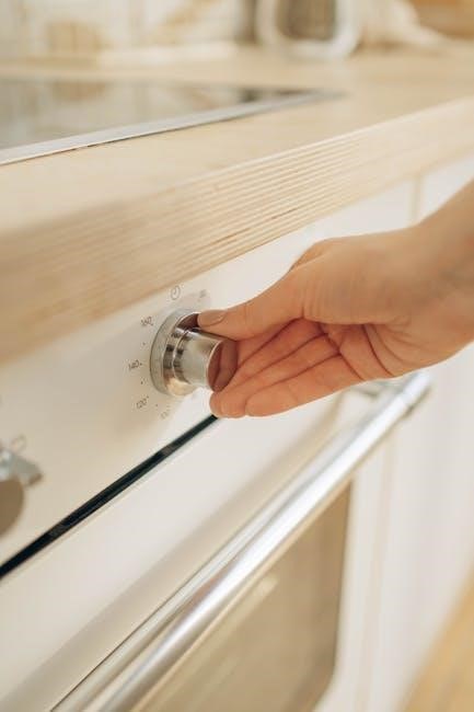
Baking Settings & Temperatures
Hotpoint stoves offer varied baking settings to suit different recipes․ Standard bake is ideal for most cookies‚ cakes‚ and casseroles‚ typically between 325°F and 375°F․ Convection bake‚ if available‚ uses a fan for even heat distribution‚ reducing cooking time and temperature by 25°F․
Always preheat the oven before baking for consistent results․ Refer to your recipe for specific temperature and time guidelines․ Use an oven thermometer to verify accuracy‚ as oven temperatures can vary․ Avoid overcrowding the oven‚ as this can hinder proper air circulation․
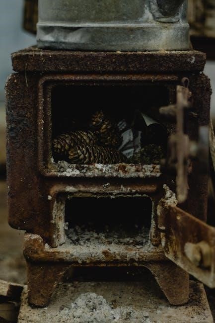
Dealing with Vintage Hotpoint Stoves
Vintage Hotpoint stoves‚ like the RJ745G0T1BG model‚ present unique challenges due to parts scarcity․ Locating information online can be difficult‚ as older models aren’t always well-documented․ Utilizing GE parts catalogs is often essential‚ as GE acquired Hotpoint․
Cross-referencing similar model numbers within the GE catalog can help identify compatible components․ Online forums‚ such as DoItYourself․com and Reddit’s r/appliancerepair‚ are valuable resources for advice and shared experiences․ Posting photos of your stove can aid in identification and parts sourcing․
Locating Information for Older Models (RJ745G0T1BG Example)
Finding details for vintage Hotpoint stoves‚ such as the RJ745G0T1BG‚ requires resourceful searching․ Direct online searches often yield limited results‚ as documentation is scarce․ GE’s acquisition of Hotpoint makes GE parts catalogs a primary resource for identifying compatible components․
Community forums like Reddit’s r/appliancerepair can provide assistance; posting photos of your specific model is highly recommended․ Even GE’s customer support may be unable to help directly with very old models․ Success often relies on comparing your stove to similar models and utilizing cross-referenced parts lists․
Using GE Parts Catalogs for Vintage Compatibility
Leveraging GE parts catalogs is essential when sourcing components for older Hotpoint stoves․ Since GE owns Hotpoint‚ many parts are interchangeable or have direct equivalents․ These catalogs‚ often available online or through appliance parts retailers‚ allow you to identify parts based on model numbers or visual comparisons․
When your Hotpoint model is difficult to find directly‚ searching for similar GE models from the same era can reveal compatible parts․ Carefully review diagrams and part numbers to ensure a proper fit․ This method proved successful in restoring functionality to a vintage Hotpoint stove‚ demonstrating its practical value․
Appliance Registration
Registering your Hotpoint stove is a vital step for ownership․ Recording the model and serial numbers ensures efficient warranty service and facilitates important safety notifications․ Manufacturers use this information to contact owners about recalls or updates․ This documentation is also crucial when contacting customer support or ordering replacement parts․
You can typically register your appliance online through the manufacturer’s website․ Keep a record of the registration confirmation for your records․ Having this information readily available streamlines any future service requests and protects your investment‚ offering peace of mind throughout the appliance’s lifespan․
Importance of Recording Model and Serial Numbers
Accurately recording your Hotpoint stove’s model and serial numbers is paramount for several reasons․ These unique identifiers are essential for warranty claims‚ ensuring you receive appropriate service and coverage․ They also facilitate the ordering of correct replacement parts‚ preventing compatibility issues․
Furthermore‚ these numbers are vital for accessing specific troubleshooting information and manuals tailored to your exact appliance․ Keep this information in a safe‚ accessible location – a home inventory or with your appliance documentation․ Having these details readily available saves time and frustration when seeking assistance or repairs․
Where to Register Your Appliance
Registering your new Hotpoint stove is a simple yet crucial step in ownership․ While direct registration details aren’t explicitly stated‚ appliance registration is generally completed through the manufacturer’s website – typically GE Appliances‚ as Hotpoint is a GE brand․
Locate the registration section on their site and input your model and serial numbers․ This process ensures you receive important safety notifications‚ product updates‚ and warranty information directly․ Keep your proof of purchase alongside your recorded appliance details for streamlined service should the need arise․
Aluminum Foil Usage (and Misuse)
Using aluminum foil in your Hotpoint oven requires caution․ While it can be safely used to catch drips on the bottom rack‚ improper use can cause damage․ Never line the entire oven floor with foil‚ as this can trap heat and affect baking performance․

Avoid using foil on the broiler pan‚ as it can reflect excessive heat and potentially ignite grease․ Be mindful of potential hazards associated with improper foil placement‚ ensuring it doesn’t interfere with heating elements or ventilation․ Always prioritize safe cooking practices when utilizing foil in your oven․
Safe Use of Aluminum Foil in the Oven
When utilizing aluminum foil in your Hotpoint oven‚ prioritize safety and functionality․ It’s acceptable to place foil on the bottom rack to catch spills and drips‚ simplifying cleanup․ Ensure the foil is shaped to avoid obstructing air circulation or touching heating elements․
Avoid extending foil up the oven walls‚ as this can disrupt heat distribution and impact cooking results․ For roasting‚ foil can be used to tent food‚ preventing over-browning‚ but never directly beneath the broiler․ Always supervise when using foil and remove it after cooking․
Potential Hazards of Improper Foil Use
Improper aluminum foil usage within your Hotpoint oven presents several risks․ Direct contact between foil and heating elements can cause short circuits or damage the oven․ Blocking ventilation with foil leads to uneven cooking and potential fire hazards․
Using foil on the oven floor without proper shaping can trap heat‚ damaging the enamel coating․ Acidic foods reacting with foil may release metallic flavors into your dishes․ Never use foil to line the entire oven bottom‚ as it hinders self-cleaning cycle effectiveness and poses a safety concern․